NAME(S) ____________________________________________________________________
CS 341 – Lab 6
Computer Architecture and Organization
Passive Sensors - Detecting Light and Motion
Equipment: Arduino UNO microcomputer, PC with Arduino IDE installed, and a USB cable.
CdS PhotoSensitive Resistor(s), 10K Ohm Resistor, and Parallax PIR Motion Sensor
Passive sensors detect some physical phenomena and
provide some amount of information about it that can be used for action or
reaction. If sensors are passive, they may
have an advantage over active sensors in some situations. Active sensors send out some kind of physical
signal and read back some reaction to the signal from the environment. Passive sensors do not. However, the emission of a physical signal
can be detected by an adversary such as an enemy in wartime. For example, RADAR can detect incoming enemy aircraft,
ships, or vehicles, but it is active because it has to send out a radio signal
to work. An enemy may use that radio
signal as a homing beacon for a guided missile to destroy the RADAR antenna/installation. A passive system is less vulnerable and the
enemy may not even know that it is there.
A photosensitive resistor (PSR) has a resistance
value that depends on the amount of light striking its sensor surface. When you connect a PSR in series with a standard
fixed resistor between a voltage source and ground, the amount of current
flowing and hence the voltage across the fixed resistor will change with the
level of light. This allows an Arduino program to detect the light level based on an
analog input connected to the junction between the PSR and the fixed resistor.
The Parallax Passive Infrared Motion Sensor (PIR) allows
an Arduino program to detect motion. Here is the data sheet for the Sensor: 555-28027-PIRSensor-v2.1.pdf. Please note that the SW shown is for a
different microprocessor and IDE so you can only follow the general outlines
and/or design of the code provided there.
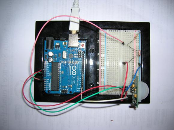
Your assignment is to connect a PSR circuit and a PIR
to the Arduino board.
Disconnect the Arduino board from the USB
port. Connect the appropriate devices
and wires to the Arduino UNO via the breadboard. NOTE:
When you are adding, changing, or removing wiring on a prototype connected to
the Arduino UNO board, always disconnect the power
from the USB port and check your wiring carefully before reconnecting it to the
USB port. Otherwise, you may damage the Arduino board. If you have any doubts, show your wiring
to the TA before reconnecting it to the USB port.
Select a 10K resistor and a PSR from the parts
provided. Connect them in series between
power and ground according to the following schematic diagram. Connect the junction between the two
resistors to the Arduino analog input pin A0.
The PIR device requires +5V power and ground plus a
signal line for one bit of data connected to digital pin 2 of the Arduino.
Connect the PC to the Arduino
UNO board using the USB cable. Open the Arduino.exe program. Write the code for the sketch to read the
analog input A0 value from the junction of the PSR and fixed resistor to display
it on the monitor screen. Also, read digital
input 2 as HIGH or LOW value from the PIR device and use that value to control
the LED on the board via pin 13.
In the setup function for this sketch, you need to initialize
the serial port for 9600 bps, setup the LED pin for OUTPUT, and setup the PIR
pin for INPUT.
In the loop function for this sketch, you need to
read the analog port A0 and print the value.
You may want to output a string of * characters proportional to the
value read from the port for a better visual display of the data. Then, read the PIR input pin and set the pin
13 LED on or off based on the HIGH or LOW value from the PIR input.
Once you get it working correctly, try some
experiments with different motion and/or light sources at different distances
and angles from the sensors. Record your
results for your report.
As a team, write your lab report to explain what you
did, how you did it, and what you learned about interfacing hardware to a
microprocessor and its software (the “sketch”).
Turn in your report including a copy of your team’s final “sketch” at
your next lab session.
___ / 10