NAME(S) ____________________________________________________________________
CS 341 – Lab 9
Computer Architecture and Organization
Controlling the Position of a Servomotor
Equipment: Arduino UNO microcomputer, PC with Arduino IDE installed, and a USB cable.
Parallax
4-6 VDC Standard Servo, CdS
PhotoSensitive Resistor, 10K Ohm Resistor, and 9Volt battery
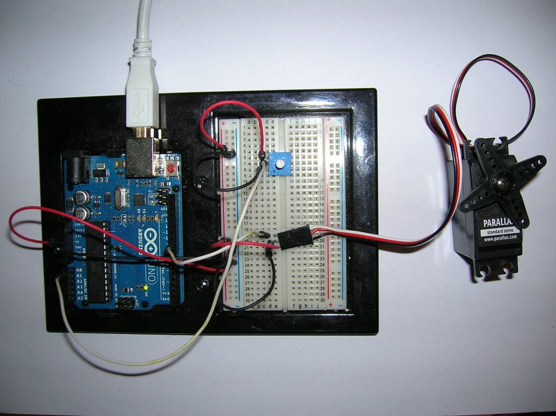
Your assignment is to connect a standard servomotor
to the Arduino board and control the position of its arm. This is a commonly required function in
programming a robotic device. In manufacturing,
a servomotor may control a robot arm to hold a tool in position for the
required work. In a remote controlled
hobby plane or a military drone, a servomotor may position a flight control
surface. In a petroleum or chemical
plant, a servomotor may open or close a valve controlling flow in a pipe.
The Parallax
Standard Servo DataSheet provides information on
programming the position of the servo.
As in previous Parallax datasheets, the software examples shown are
based on a different language and library so you can only use it for guidance
and cannot use that code directly in our project.
We need to include the Arduino <Servo.h> library in our C code. It has a definition for a Servo class. We will use the Servo class “attach” method
to configure a Servo object to use a Pulse Width Modulation (PWM) output pin by
number. Like the digital output pin on
which it is based, a PWM pin can generate only a +5 volt and 0 volt level. However, a PWM output pin can be modulated
(changed in value) at a very fast rate (or as we might say with a short duty
cycle). For example, if the pin is set
to +5 volts half the time and 0 volts half the time quickly enough, the net
voltage will behave like an analog 2.5 volts.
Similarly, if the pin’s voltage is set to +5 volts for a larger
proportion than half of the time, the net voltage will be higher than 2.5
volts. If it is set to 0 volts for a
larger proportion than half of the time, the net voltage will be lower than 2.5
volts. This is an inexpensive way to use
digital outputs to create outputs that behave like analog outputs.
The Servo class contains a “write” method that takes
an int value and sets the duty cycle of the attached PWM
pin to the corresponding effective analog voltage. With the Standard Servo used in this
assignment, the int value is scaled to a value
between 0 and 180 corresponding to the desired position of the servo’s arm in a
semicircular arc. We will use the
Arduino math library function “map” to scale an int
input value to a value to be written to the servo.
We will use a real analog input to control the
position of the servo. We will connect a
potentiometer (a “pot”) across +5 volts and ground (0 volts) and connect the
center tap wire to the Arduino analog input pin A0. (A pot is an electronic component
traditionally used for volume controls on audio devices and for other analog
control purposes.) The center tap is controlled by the position of a knob/shaft
and in each position it presents a voltage value that varies between 0 and +5
volts on the wire to the input pin. We
will use the library analogRead function to read an int value between 0 and 1023 that corresponds to the
voltage/position of the knob/shaft on the pot.
DON’T FORGET TO DETACH THE BATTERY WHEN YOU FINISH
THE LAB EXERCISE!
NOTE: When you are adding,
changing, or removing wiring on a prototype connected to the Arduino UNO board,
always disconnect the power from the USB port and check your wiring carefully
before reconnecting it to the USB port.
Otherwise, you may damage the Arduino board. If you have any doubts,
show your wiring to the TA before reconnecting it to the USB port.
In your sketch, you need to include the <Servo.h> library header file and define a global Servo
object. In your setup code, you need to
use the Servo’s attach method to attach it to pin 9 (the PWM digital output
pin). In your loop code, you need to use
the analogRead function to read the value on A0 (from
the pot), map the 0 - 1023 range of values to 0 - 180 via the map function, and
pass that value to the Servo’s write method as a parameter. Afterwards, delay for 15 millisecs
(to allow time for the servo to react to the new position setting). Load your sketch to the Ardino.
Disconnect the Arduino board from the USB port. Connect the power and ground wires to the pot
and the servo. Connect the Arduino
digital pin 9 to the control wire to the servomotor and analog input A0 to the
center tap on the potentiometer. Attach
the 9V battery with the pigtail.
When you have it working
correctly, you should be able to turn the knob/shaft on your pot and see that
the servomotor turns and holds the new corresponding position.
Disconnect the pot and set up a voltage divider using
the PSR and the 10K resister as in Lab 6.
Connect the junction between the two resistors to Arduino pin A0 instead
of the center tap of the pot. Show that
you can control the servo position based on the light level at the PSR.
Show your two experiments to the TA to get credit
for this lab.
DETACH THE BATTERY TO PREVENT IT FROM CONTINUING TO
RUN THE ARDUINO BOARD AND DYING IN THE BOX!
As a team, write your lab report to explain what you
did, how you did it, and what you learned about interfacing hardware to a
microprocessor and its software (the “sketch”).
Turn in your report including a copy of your team’s final “sketch” at
your next lab session.
___ / 10