CS641 Class
14
Last time:
AND, OR, NOT gates
Read:
Appendix C, on CD-ROM, logic handout linked from syllabus
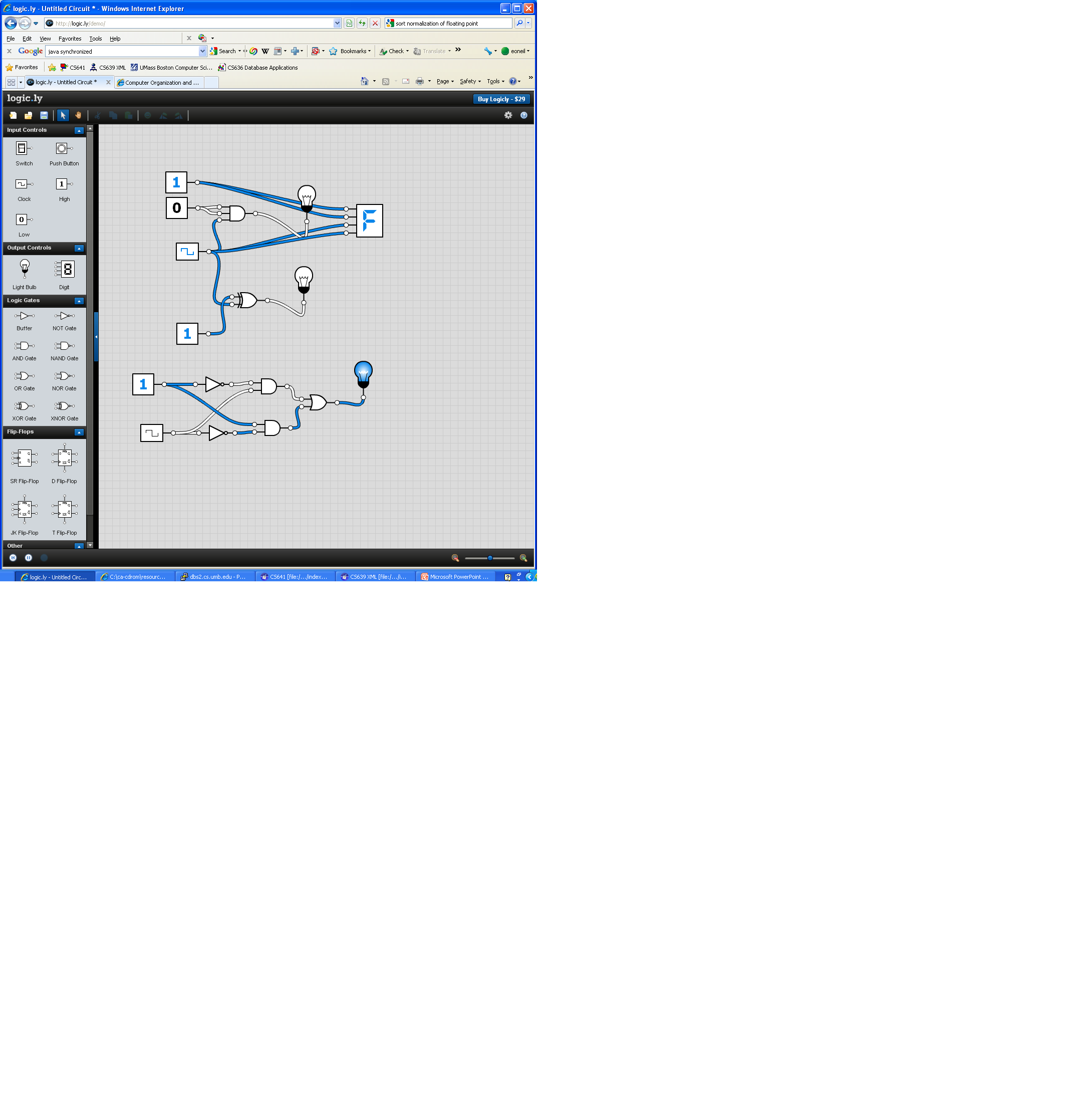
Demo using
simulator at http://logic.ly/demo/
1. Hook up AND with inputs of 1 and clock, output of light-bulb, see light go on and off
2. Hook up AND with output to digit display
3. Hook up XOR
4. Hook up XOR made of simple gates:
5.

Combinational Logic
° Complex logic blocks are built from these 3 building blocks.
° A combinational logic block is one in which the output is a function only of its current input.
° Combinational logic cannot have memory (e.g., a register is not a combinational unit). More about memory later…
What are common
larger combinational blocks (built from gates)?
2-Input Multiplexor (MUX): controls which input gets
through

That’s not really a “truth table” though, need to show what happens with all 3 inputs:
|
A |
B |
D |
C |
|
0 |
0 |
0 |
0 |
|
0 |
0 |
1 |
0 |
|
0 |
1 |
0 |
0 |
|
0 |
1 |
1 |
1 |
|
1 |
0 |
0 |
1 |
|
1 |
0 |
1 |
0 |
|
1 |
1 |
0 |
1 |
|
1 |
1 |
1 |
1 |
Not very helpful to read.
General Multiplexors:
• have control bits and data bits
• control bits select which data bit will pass through: all others are blocked
• in general, 1 control bit selects between 2 data bits, 2 control bits select between 4 data bits, 3 control bits select between 8 data bits, n control bits select between 2n data bits
so we can build a
mux of any size to serve our purpose
Using MUXes
° Used to select one of N different inputs.
° For example, a CPU has an adder circuit to add two numbers, one operand always comes from a register.
• For an add instruction, second operand also comes from a register.
• For an addi instruction, second operand is immediate within the instruction.
• Implemented in hardware with a MUX.
° Much more detail later…
Another Important Combinational Circuit: Decoder
The inputs say which output number to make 1, rest 0
i.e., if A,B is a
code, it specifies which outbound device to activate (say)


Using Decoders
° Complementary to MUXes
° Example: MUX to select operand to adder. Where does the input signal to the MUX come from?
° A decoder attached to the instruction opcode field distinguishes add from addi to control the MUX!
So how do we implement combinational logic?
Two-Level Logic
° Any combinatorial logic block, not matter how complex can be written as a OR of many ANDs using NOTs
° Called “sum-of-products”in Boolean algebra
• Sum à boolean OR
• Product à boolean AND
° Can convert any truth table to sum-of-product form
Simplistic approach:
write a product (ANDs) for each line in the truth table, then sum (OR) all the
products
Boolean shorthand notation
° Shorthand Notation:
• . (or implied) for AND
• + for OR
• or ’ for NOT
Example: using ‘ for
complement (should be overbar)
A.B.C + A.B.C + A.B.C
=
A’BC + AB’C + ABC’
=
((NOTA) AND B AND C) OR
(A AND (NOT B) AND C) OR
(A AND B AND (NOT C))
Two-Level Logic Example: Suppose we want to create
combinational logic based on the following truth table. What circuit do we need?
1. Look for all outputs = 1
2a. If input a 1, include true version of input
2b. If input a 0, include complement version of input
6. Write equation as sum (OR) of these products (AND)

Given this sum-of-products Boolean expression, it is easy to draw a circuit. Just use a 3-input AND gate with an inverter on the A input and no inverters on the B and C inputs for the first term. Similarly use 2 more AND gates for the other two terms. Then use an OR gate to do the sum of the outputs from the 2 AND gates.
Another Example: Exclusive OR
“Exclusive or”
(XOR). True if the two inputs are the different, false if the two inputs are
same
There are XOR gates,
but let’s construct XOR out of OR, AND, and NOT.
We write out the
truth table, then look for 1’s in ouput Z, write sum of products:
Hopefully Review: Laws of Boolean Algebra
° Identity: A + 0 = A, A . 1 = A
° One and Zero: A + 1 = 1, A . 0 = 0
° Inverse: A + Ac = 1, A . A’ = 0, A’’ = A (again using ‘ for complement: should be overbar)
° Communicative: A+B = B+A, A.B = B.A
° Associative:A+(B+C)=(A+B)+C; AND too
° Distributive: A.(B+C)= (A.B)+(A.C); OR too
° DeMorgan’s Theorems:
• (A + B)’ = A’ . B’
• (A . B)’ = A’ + B’
Taking advantage of sum-of-products
° Since sum-of-products is a convenient notation and way to think about design, offer hardware building blocks that match that notation
° One example is Programmable Logic Arrays (PLAs)—will look at later