CS641 Class
19
hw5 due, hw6 available, due Wed., 4/20 (Monday is a
holiday)
Last time:
Covered first part of states handout linked from syllabus
Finite State Machine Example from Handout: 3 ones…
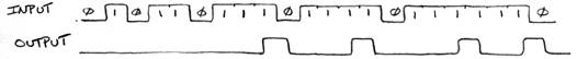
To do this, the system must be able to count ones up to 3, then start over. But it only needs memory for counts up to 2, because it can handle the last instance “on the fly”. So it only needs 3 states, S0, S1, S2 for how many ones already seen, and if in state S2 and sees another 1, report output=1.
Note fix from handout! S2 --> S0 on input = 1.
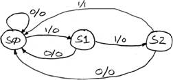
Transition Table: Three states, 00, 01, 10. PS = previous state, NS = new state
|
PS |
Input |
NS |
Output |
|
00 |
0 |
00 |
0 |
|
00 |
1 |
01 |
0 |
|
01 |
0 |
00 |
0 |
|
01 |
1 |
10 |
0 |
|
10 |
0 |
00 |
0 |
|
10 |
1 |
00 |
1 |
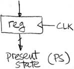
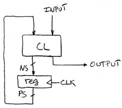
Hardware Implementation of FSM


CL logic:
NS1 = (PS0)’ * (PS1)’ * In
NS0 = (PS0)’*PS1*In
Out = PS0 * (PS1)’*In
Draw circuit: Here’s part:
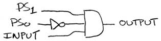
or using bubble:

General Model for Synchronous Systems
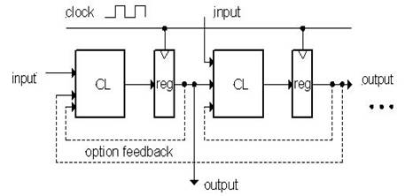
---optional feedback
Sequential Circuit Modules:
Register files & Memory
° Register files are sets of registers than can be read and written by supplying a register number to be accessed.
° Could be built out of D Flip Flops, mux and decoders.
° Packaged up as SRAM: static RAM
Like Fig. C.9.1, with 21-bit address and 16 bit data in, data out
SRAM: just flip-flops, very fast (compared to DRAM, capacitors, 50 ns delay)
Operation: Read register r, get its contents X
Put address r on Address, then assert chip select, output enable, say on clock edge.
Device puts contents of register r, i.e. X, on data-out pins by next clock edge.
Write register x with given X value
Put address x on Address, data X on data-in
Then assert chip select and write enable, on clock edge
By next clock, SRAM has stored X inside.
Inside: Address---> Decoder ---> select which internal register to work with
Route output of register to output port: need mux to do this part.
See Fig. C.8.8 for the MUX wiring, and C.8.9 for the decoder. See hw problem.
Note similar diagram on pg. 306, Sec. 4.2, our next chapter to tackle.
Traffic
Light Example
Then we looked at the traffic light example in Appendix C, pp. C-68-C-71.
Note that the FSM on pg. C-70 has wrong labels on the states: should be NSgreen and EWgreen.
We looked at the transition table on pg. C-69, which shows 2 inputs at each state, so 4 input combos. Thus we would expect 4 arrows out of each state in the FSM. But there are only 2 arrows out of each state in the FSM on pg. C-70. What gives?
We drew the FSM with 4 arrows out of each state. For example, the transitions from NSgreen are
NSgreen ---00/--->NSgreen
NSgreen ---01/--->EWgreen
NSgreen ---10/--->NSgreen
NSgreen ---11/--->EWgreen
and we see that both 00 and 10 inputs go to NSgreen, so the condition for going to NSgreen is
00 or 10 = NScar’*EWcar’ + NScar*EWcar’ = EWcar’(NScar’ + NScar) = EWcar’ (using ‘ for not again)
This says it doesn’t matter whether there’s a NScar or not, it only matters that there’s not an EWcar, for this transition from NSgreen to NSgreen.
Similarly NSgreen--->EWgreen boils down to being conditioned on EWcar
That shows how the FSM on pg. C-70 is right.
We can show this simplificaton in the transition table too, using “don’t care” X values: The first 4 lines of the table become:
Nsgreen X 0 NSGreen
NSgreen X 1 EWgreen
Review…
° We use feedback to maintain state: how a flip-flop works
° D-FF: we use it as a crucial building block, appreciate its ability to snapshot inputs
° D-FlipFlops are used for Registers
° Clock edges signal when a register loads a new value
• Setup and Hold times important to make sure the circuit actually works
° Pipeline a big-delay CL for faster clock (i.e., add an intermediate register)
° Finite State Machines extremely useful to describe sequential circuits
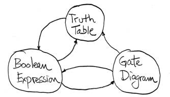
Representations of CL Circuits…
° Truth Tables
° Logic Gates
° Boolean Algebra
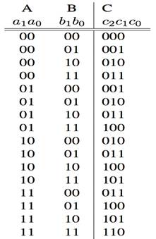
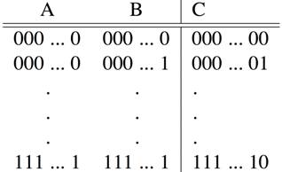
TT Example : 2-bit adder: 4 inputs, 16 lines in TT
3 outputs: 2 for number, one for carry
TT Example: 32-bit unsigned adder: TT has 2^64 rows!
Boolean Algebra: Circuit &
Algebraic Simplification
Note Power of Boolean Algebra to
simplify circuits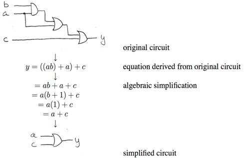
Similarly, get sum-of-products
and boil down before specifying circuit
Summary of 3 ways to specify a
Combinational Circuit:
We’re working our way up to the CPU, need expertise in certain circuits...