CS641 Class 21
°
Adder/Subtracter – One-bit adder, for ith bit:
°
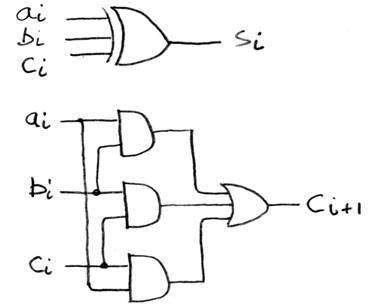
N 1-bit adders Þ 1 N-bit adder
Yes, for unsigned
numbers, but what about signed?
°
Consider
a 2-bit signed # and overflow conditions:
•
10 =
-2: adding -1 or -2 to it gives overflow
•
11 = -1:
adding -1 works, but adding -2 gives overflow
•
00
= 0: no problems here
•
01
= 1: adding 1 to it overflows
°
what
turns out to be important is the “carry-in” and “carry-out” of the highest digit
°
from
above pic, carry-in = Cn-1 , Carry-out
= Cn
°
for two
digits
•
C1
= Carry-in = Cin, C2 = Carry-out = Cout
•
No Cout
or Cin --> NO overflow!
•
Cin,
and Cout--> NO overflow!
•
Cin,
but no Cout--> A,B both > 0, overflow!
•
Cout,
but no Cin --> A,B both < 0, overflow!
°
Overflows
when…
![]()
Back to Verilog
Go over intro examples again, with some more notes—
mynand.v
Note that input and
output signals are wires in type, not reg’s.
Output can be of type reg, though as we will see later.
In the assign, the
lhs (left-hand-side) must be a wire, but the rhs can use wires and regs.
mynand_tb.v:
Note all these reg’s are holders of bits, but not real circuit registers. Only
in certain circumstances do reg’s turn into real registers in the constructed
circuit—I’ll alert you to this. Here the
reg’s help us set up useful bit patterns for testing the circuit, like the
switches in logic.ly setups.
The code inside
iniitial is sequentially executed, with time delays as programmed.
The monitor is
watching the signals listed in its arg list, but only the ones actively
involved in the circuit. Monitor doesn’t care if you change a reg that is not
connected to an input to a module, for example, or the changes in $time.
We know it takes a
little time for the inputs to nand1 to be reflected in its output, so you might
expect monitor to print two lines, one for the inputs changing and one for the
outputs. But we haven’t specified any delay in the module, so Verilog treats it
all as one moment, and outputs only one line at the end of this moment.
rsff.v
Here we see a signal
value of “x”, for unknown. Another special value is “z”, for Hi-Z (high impendence)
signals, ones that are effectively disconnected even though wired to
something. This is used in bus
connections: only one device can drive the bus at a time, so the rest express z
outputs.
OK, now look at CS61c Tutorial (linked to syllabus)
mux2
Note the nameless
gate modules here: It’s “and (w0, s0, in0)”, not “and x(w0, s0, in0)”, the
syntax we’ve seen so far to give a name “x” to the instantiated module. This is allowed for the built-in gates, but
not user-defined modules.
With gates, what’s
important is what they are wired to, so they don’t need a name. We traced out the circuit from the code.
Note that the
circuit boils down to a simple logical expression. So instead of all the gates
we could just use a one-liner with assign:
assign out =
select&in1|~select&in0;
This is noted on pg.
18.
Verilog lets us
design with gates or Boolean expressions.
It turns the Boolean expression into gates internally.
Skip the delay
example for now and go to Bit Vectors & Looping, pg. 7
reg[2:0] c; sets up a 3-bit reg, bits c[0], c[1],
c[2] (high bit)
c is used to hold
the 3 bits of input needed for the mux2 device
See 3-bit constant,
also 1-bit constants.
Repeat construct, so
we don’t have to write out all the cases
Note that the output
shown on pg. 8 is for the mux2 with internal delay.
We worked out the
output for the no-delay case:
c out expected time
000
x 0 0
001 1
1 10
010
0 0 20
011
1 1 30
100
0 0 40
101
0 0 50
110
1 1 60
111
1 1 70
Now consider adding
delay: 2 time units between input and output of the mux2, so monitor usually
reports 2 lines of output, one for the inputs changing and one for the outputs
changing 2 time units later.
But in two cases, as
we can see above, the outputs didn’t actually change, so monitor didn’t output
a second line. Causes confusing output.
Another reporting
capability, strobe, can be used to avoid this problem.
mux4, pg. 10
We drew the circuit
following the code, to see the hierarchy of mux2’s.
Next example:
Register, but let’s look at the DFF, pg. C-53 first, next time.