Operating System-Class 12-March 4th
Last time: programming serial ports using inb/outb
-- no interrupts
We worked with 3 device registers
COM2:
1. receiver data register(read only) port 0x2f8: inb %dx, %al
ch = inpt(COM2_BASE + UART_RX)
Tutor>pd 3f8 ==> returns 16 ports
2. transmitter data register(write only) port 0x2f8: outb %al, %dx
outpt(COM2_BASE + UART_TX, ch)
Tutor>ps 3f8 ==> 41
 |
3. line status register. port 0x2fd: inb %dx, %al
status = inpt(COM2_BASE + UART_LSR)
Tutor>pd 3fd
Total: 8 ports, >8 device registers
Timer device: timer 0 of 3-timer chip.
-- has 2 ports(8 bits each)
count register at port 0x40
control register at port 0x43
Where do these port #s come from?
Answer: the wiring of the device into the system
-- not the device itself
-- not the CPU
done to avoid overlaps in ports in use.
Timer device
The timer device of the PC is a chip (or anyway digital logic) that contains a 16-bit counter and some logic controlling it. A counter is a register (array of bits) plus some logic to increment and/or decrement the number in the counter. In this case the counter decrements, so we talk of “downcounts.”
The Timer has a 16-bit counter in it.
-- it down-counts the contents of the counter on each pulse coming in from an oscillator(1.193M cys/sec)
 |
The timer device is connected to a crystal oscillator that puts out a simple square wave at 1.193 Mhz, i.e., one cycle every microsecond (a little under.) On every cycle of the oscillator, the counter decrements by one. Eventually the count reaches zero. At this point, it reloads the initial count from the holding register and starts down-counting again. In addition, at each zero it sends an IRQ signal out. This happens over and over.
 |
say 10000 – fits in 16 bit (64k-1 fits 16 bits)
total 10000/1.193 = 10ms(provided init – needed for OS)
max init count 64k-1
total (64k-1)/1.193 = 55ms
Mystery: How can we specify a 16-bit initial count using the 2 8-bit ports?
Answer: hardware designer specified this protocol for this.
1. 0x34 outb to control register: outb %al(0x34), %dx(0x43)
2. less significant 8 bits of init count – outb to count register
3. more significant 8 bits of init count – outb to count register
Inside:
1. the timer logic assembles the 2 8-bit parts of the init count into a 16-bit holding register separate from the main counter.
2. load the counter from holding register.
Pharmacy analogy
Suppose a pharmacy has only a tiny slot for the Rx number and a button marked “Refill prescription”. Slips of paper are provided with space for half of the Rx number. The protocol for refilling a prescription is:
1. push the refill button
2. feed the first half of the Rx number through the slot
3. feed the second half of the Rx number through the slot
On the other side, the pharmacist hears a beep, receives the first half and puts it in a holder, then the second half and puts it in the holder next to the first half. Thus the full Rx number is reassembled and the pharmacist knows what to do.
Hardware ports provide similar “portals” for data going to and from the hardware.
Reading the timer’s 16-bit counter:
1. send “latch command” 0x00 to control port
2. read count port for LS byte
3. read count port for MS byte
Inside:
1. latch the 16-bit counter value into the holding register
2. detect read of 8-bit count, reply with LS byte from holding register
3. detect a second read, reply with MS byte from holding register
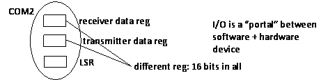
Interrupts
--x86 case only
covered in Love: Chapter 6, to start to p77, stops at “Top …”, skip to p92 “Summary”
PIC ---- secretary to the CPU
-- receive events from outside world, like secretary receives phone calls
-- decides on most important & relay it to boss
PIC can be told to ignore ints for certain devices, and it prioritizes ints by device.
x86: uses IRQ number
It is crucial to think of each of the three participants in an interrupt as “living” an independent existence. Each can hold state (remember things) in hardware registers and is responsible for certain behavior over time.
The Big Picture again:
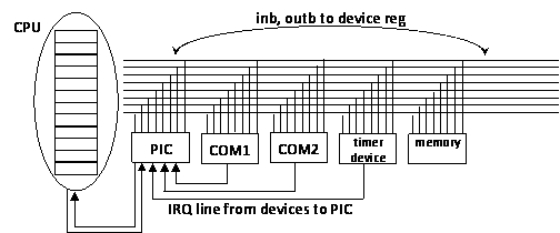 |
interrupt signal device event examples:
Ex. COM2 has a char ready to read
COM2 is ready for another transmit char
timer 0 – down count reaches 0
Steps after a COM port receives a char.
-- signals on its IRQ line to PIC
-- it expects a read to come in for the char(execution of code in OS/program)
-- meanwhile it is in interrupt level/state
-- eventually it detects the read(inb) and answer with the char(clears the DR bit), and forgets about the interrupt
Note that only the receiver is in “interrupt state”, not the transmitter. It is happy to transmit chars while this is going on in the receiver.