NAME(S) ____________________________________________________________________
CS 341 – Lab 1
Computer Architecture and Organization
Introduction to the Arduino Microcomputer
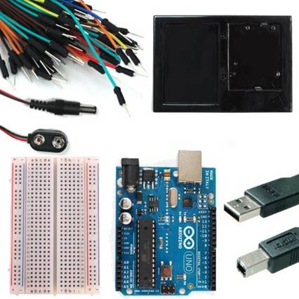
Equipment: Arduino UNO microcomputer, PC with Arduino IDE installed, and a USB cable. Prototyping components and wires.
The Arduino microcomputer is a low end
microprocessor on a small printed circuit board. In our lab configuration, it includes a small
breadboard for prototyping and connecting peripherals.
In our lab, the Arduino UNO will be the target host
for our experiments and the PC attached to it via the USB cable will be the
development host. You will use the
Arduino.exe IDE program to edit, compile, download, and monitor the execution
of your “sketches” (experimental programs).
The “sketch” software is written in a language that is almost exactly
like C. There are a few extensions to
the language and a custom library to access the peripheral hardware input and
output ports.
Your first assignment is to set up your Arduino
system and run the example “Blink” program.
Connect the PC to the Arduino UNO board using the
USB cable. Open the Arduino.exe program.
Use the menu: File >>
Examples >> 01.Basic. Select the
Blink program which will open a new window containing the source code for the Blink
program. Use the “right arrow” icon on
the top tool bar to compile and upload/run the code on the Arduino board. Watch the LED’s on the Arduino board during
the upload to observe it occurring. Once
the program starts running, the yellow LED will be flashing at a rate of one
second on and one second off.
Now study the code in the source of the sketch. Find the lines that control the flash rate
for the blinking LED. Change those lines
to slow down the flash rate to one half of the current rate. Repeat the steps for compiling, uploading,
and running your modified code. Show the
TA when you have this working.
Now disconnect the Arduino board from the USB
port. NOTE: When you are adding, changing, or removing wiring on a prototype
connected to the Arduino UNO board, always disconnect the power from the USB
port and check your wiring carefully before reconnecting it to the USB port. Otherwise, you may damage the Arduino board. If
you have any doubts, show your wiring to the TA before reconnecting it to the
USB port.
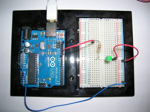
Insert an LED and a resistor in series on the
breadboard to pin 12 on the Arduino board following the design shown in this
picture. The longer leg on the LED
should be connected to the resistor.
The resistor should be 470 ohms which you can
determine from the color of the bands around the body of the resistor (yellow,
violet, brown). See the standard resistor
color code table:
First Band Second Band Third
Band
Black 0 0 no zeros
Brown 1 1 one zero
Red 2 2 two zeros
Orange 3 3 three
zeros
Yellow 4 4 four zeros
Green 5 5 five zeros
Blue 6 6 six zeros
Violet 7 7 seven zeros
Gray 8 8 eight zeros
White 9 9 nine zeros
Again study the code in the source of the
sketch. Find the line(s) that control
the pin being used to flash the LED.
Change the line(s) to use pin12 instead of pin 13 to flash the LED on
your breadboard. Repeat the steps for
compiling, uploading, and running your modified code. Show the TA when you have this working.
Naturally, you want to run your embedded system
without an “umbilical cord” to a development station. A mobile device usually has its code stored
in a non-volatile memory and is battery powered. Disconnect the Arduino from the USB
cable. Plug the battery pigtail into the
connector next to the USB connector on the Arduino board. It should power up and run your sketch
independently. Now it is portable.
DISCONNECT THE BATTERY PIGTAIL BEFORE PUTTING THE
KIT BACK IN THE STORAGE CONTAINER.
As a team, write your lab report to explain what you
did, how you did it, and what you learned about interfacing hardware to a
microprocessor and its software (the “sketch”).
Turn in your report at your next lab session.
___ / 10