NAME(S) ____________________________________________________________________
CS 341 – Lab 5
Computer Architecture and Organization
Embedded System “Hello World” Display and Use of Sound
Equipment: Arduino UNO microcomputer, PC with Arduino IDE installed, and a USB cable.
Parallax 2x16 Serial LCD, Backlit with Speaker.
The Parallax LCD Display allows an Arduino program to display two lines of text with sixteen
characters per line as well as play sounds through a piezoelectric
speaker. Here is the data sheet for the
LCD display: 27976-7-9-ParallaxSerialLCD-v2.1.pdf. Please note that the SW shown is for a
different microprocessor and IDE so you can only follow the general outlines
and/or design of the code provided.
The above data sheet does not cover the
piezoelectric speaker. To play tones
instead of writing characters to the display, you send a sequence of non-ASCII
character values to the device. Write
the code value for any control functions before writing the code value for a
tone. The following is a list of tones
you can generate and how to control the length or octave for each tone.
Character Value Control
Function or Tone
0xD0 Set 1/64th note length
0xD1 Set 1/32nd note length
0xD2 Set 1/16th note length
0xD3 Set 1/8th note length
0xD4 Set 1/4 note length
0xD5 Set 1/2 note length
0xD6 Set whole note length
0xD7 Set Lowest octave
0xD8
0xD9
0xDA
0xDB Set Highest octave
0xDC A
0xDD A# / B flat
0xDE B
0xDF C
0xE0 C# / D flat
0xE1 D
0xE2 D# / E flat
0xE3 E
0xE4 F
0xE5 F# / G flat
0xE6 G
0xE7 G# / A flat
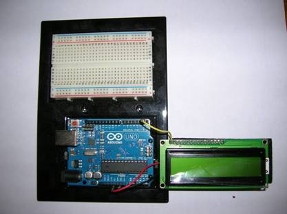
Your first assignment is to connect the serial LCD
to a serial port on the Arduino UNO. The device requires +5V power (red wire) and
ground (black) plus one signal line for receiving serial data (yellow). Disconnect the Arduino
board from the USB port. NOTE: When you are adding, changing, or
removing wiring on a prototype connected to the Arduino
UNO board, always disconnect the power from the USB port and check your wiring
carefully before reconnecting it to the USB port. Otherwise, you may damage the Arduino board. If you have any doubts, show your wiring
to the TA before reconnecting it to the USB port.
Check the switches on the back of the board. (See
figure on page 2 of the data sheet.)
Select the setting for 9600 bps.
Connect the appropriate wires to the Arduino
UNO either directly or via the breadboard if the display wires are not long
enough. The signal wire should be
connected to pin 3.
You will program pin 3 as the transmit data pin for
a software defined serial port (UART TXD).
Note that we are using the serial interface at 0-5VDC as at the pins on
the UART – not at the +12VDC and -12VDC as at an RS-232 D-connector after
voltage shifting. NOTE: Do not
connect the Arduino serial port pins to the pins on a
D-connector RS-232 interface. Otherwise,
you may damage the Arduino board.
Connect the PC to the Arduino
UNO board using the USB cable. Run the test suggested on page 2 of the data
sheet. If needed, adjust the contrast
with a screwdriver as explained there. Don’t
forget to reset the switches to 9600 bps.
Open the Arduino.exe program. Write the code for the sketch to display
“Hello World!” on the display. Define
the serial port object by including SoftwareSerial.h
and defining a reference variable for a SoftwareSerial
object with whatever RX pin number and TX pin number we are using:
//
Instead of Java: SoftwareSerial
serial_display = new SoftwareSerial(rxpin, txpin);
SoftwareSerial serial_display(rxpin,
txpin);
The Arduino compiler can instantiate the object using the two parameter
constructor without use of the “new” operator.
The compiled code calls the constructor, passes the parameters provided,
and sets up the reference variable. This
is one of the syntactical differences between the C++ and Java languages.
In the setup function for this sketch, you need to:
Use the serial display object’s member functions
(methods to you Java OOP folks) begin and write. The begin member function is used to set the
baud rate for the serial port. Set it to
the same value as the switch settings on your display device (probably 9600
bps). The write member function is
overloaded, so you can call it passing either a single ASCII character (0xhh or
‘c’) or a String enclosed in double quotes.
Write code to clear the display and display the text
“Hello World!”.
Write code to use the piezoelectric speaker
functions. For example, the tune for “Charge!”
can be played using: 1/16th
G, C, 1/8th E, 1/4 G, 1/8th E, 1/2 G. Go ahead and drive the TA crazy with that or
a tune of your own choosing. ;-) Try it in different octaves.
If you have additional time, try some experiments
with other text or sounds.
You can write some code in the loop function if you
want to experiment with that capability.
If you do, it would be a good idea to include one or more delay() calls
in the loop function so that you have time to see or hear the results of each
pass before the next pass is made.
As a team, write your lab report to explain what you
did, how you did it, and what you learned about interfacing hardware to a
microprocessor and its software (the “sketch”).
Turn in your report including a copy of your team’s final “sketch” at
your next lab session.
___ / 10