NAME(S) ____________________________________________________________________
CS 341 – Lab 8
Computer Architecture and Organization
Getting a Buzz On (Without Alcoholic Beverages)
Equipment: Arduino UNO microcomputer, PC with Arduino IDE installed, and a USB cable.
3VDC Vibration Motor, Transistor, Diode, Capacitor, and Resistors
Your assignment is to connect a vibration motor to
the Arduino board. Disconnect the
Arduino board from the USB port. Connect
the appropriate wires to the Arduino UNO via the breadboard. NOTE:
When you are adding, changing, or removing wiring on a prototype connected to
the Arduino UNO board, always disconnect the power from the USB port and check
your wiring carefully before reconnecting it to the USB port. Otherwise, you may damage the Arduino board. If
you have any doubts, show your wiring to the TA before reconnecting it to the
USB port.
There is a limit to the current that an Arduino
output pin can supply. In order to
provide the larger current needed to run the vibration motor, we use an
external 2N2222 transistor as a current controlling
switch. See this schematic diagram.
A transistor has three leads. The emitter lead is connected to ground. The base lead is connected to a control
source (the Arduino output pin). The
collector lead is connected through a load (the motor and the 20 Ohm resistor)
to the supply voltage. When no current
flows from the Arduino pin through the 1K resistor and base lead to ground
through the transistor, the transistor is turned off and no current will flow
through the 20 Ohm resistor and the load (the motor). When current does flow
from the Arduino pin through the 1K resistor and base lead to ground through
the transistor, the transistor turns on and current will also flow through the
20 Ohm resistor and the rest of the load (the motor). Hence the transistor is an electronically
controlled switch.
Notice that there are two other components as part
of the load connected in parallel with the motor. Here’s why they are used.
When a motor is running, the commutator carrying
current to the spinning armature creates sparks which can cause voltage spikes. The capacitor absorbs any voltage spikes that
occur while the motor is running and protects the rest of the circuitry. Find and use a 0.1 microFarad
capacitor with help from this Capacitor Code Chart.
When a motor is shut off, there is a collapsing
magnetic field around the coils of wire in the motor. That creates a backward voltage in the
opposite direction to the normal voltage that makes the motor turn. The diode (1N4001)
absorbs (short circuits) this current and prevents it from flowing back through
and damaging the transistor or other parts of the circuit. Normally, the voltage is applied to the load
in the opposite direction to the direction that the diode carries current so
the diode does not carry any current when the motor is running.
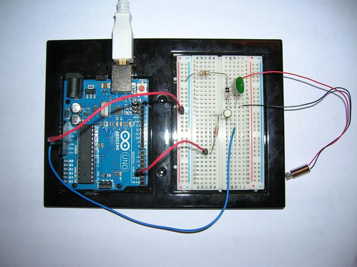
Study the following picture for implementing the
circuit shown in the above schematic.
Connect the transistor emitter to ground and the collector to the load.
Connect the transistor’s base lead through a 1K Ohm resistor to the Arduino
digital output pin 3. Connect the
components of the load together and to the transistor collector and +5 volt
power.
Connect the PC to the Arduino UNO board using the
USB cable. Open the Arduino.exe program.
Write the code for the sketch to turn on and off the digital signal on
pin 3.
In the setup function for this sketch, you need to
configure the pin 3 as an output.
In the loop function for this sketch, you need to
use calls to delay and digitalWrite to turn on and
off the signal to pin 3 according to a timed pattern. I chose 1 second on and 5 seconds off, but
you can choose your own timing.
If you have additional time, try connecting a sensor
from one of the earlier labs and use the input from the sensor to turn the
vibrator on and off.
As a team, write your lab report to explain what you
did, how you did it, and what you learned about interfacing hardware to a microprocessor
and its software (the “sketch”). Turn in
your report including a copy of your team’s final “sketch” at your next lab
session.
___ / 10